What is a Thermal Interface Material (TIM) a.k.a. gap filler?
A gap filler, as its name suggests,allows to fill the existing gaps in electronical assemblies in order to increase the thermal drain.
Air indeed has a very low thermal conductivity (0,025 W/m·K), which makes it a thermal insulator. It thus prevents heat and calories released by the component from dissipating. Gap fillers have different thermal conductivity, that can go from a few W/m.K to several thousand (on graphite materials). The thermal gain is quickly visible!

To act as a thermal bridge, a gap filler must be as flexible as possible. This is why gap fillers are mostly made out of silicone or polymers. These materials have the advantage of being flexible, stable, and able to resist a large temperature range (-40°C to +150°C,these materials are also UL94 V-0 certified for fire resistance). The drawback of these polymers is that they are poor heat conductors. This explains why the polymer is mixed to metallic or ceramic micro-particles when used to make gap fillers. These particles strongly increase the polymer’s thermal conductivity. They can be aluminium oxide, boron nitride, aluminium nitride, magnesium oxide or else.
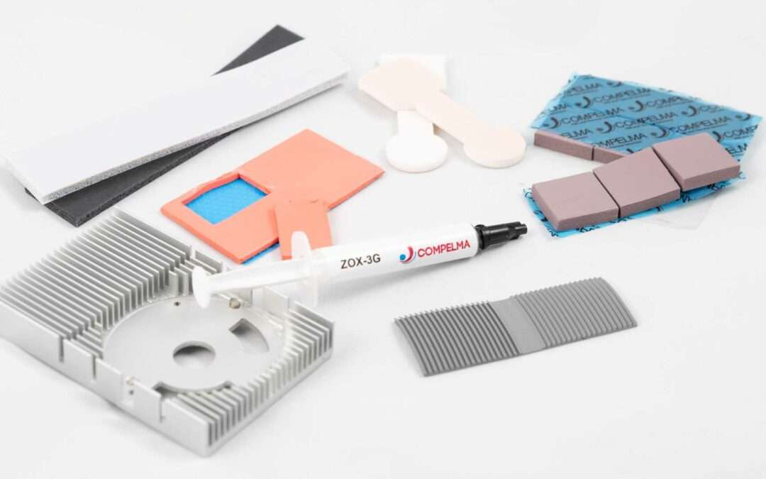
The obtained polymer is then shaped to make the gap filler. The gap filler can therefore be in the form of a solid thermal pad (or thermal blanket or thermal interface) or of a thermal paste. Each format has its advantages and drawbacks. We will come to that point.
The large range of gap fillers available on the internet can be explained by the fact that every manufacturer has its own recipe (the exact quantities are kept secret). As a result, different gap fillers have very variable densities, hardnesses and conductivities (and consequently variable prices and qualities).
What is the purpose of a thermal pad or thermal interface material?
Thermal interface materials eliminate air layers or bubbles between a component and a heat sink. The thermal interface material thus creates a thermal bridge that drains the component’s calories. These calories are then dissipated by the heat sink (extruded or machined heat sink,or directly by the foundry).

The importance of the thermal dissipation in electronic.
In electronics, mastering the temperature of a system is a key element (as well in terms of performance as in terms of longevity). On a daily basis, we all need to deal with these topics: when we use a computer, a game console or a phone. The overheating of an equipment leads to an immediate decrease of its performances, and sometimes a risk for its safety. With the miniaturization and ever higher performance levels of electronic components, thermal dissipation becomes more and more critical.
Usually, the default rate of an electronic equipment doubles for every 10°C increase in junction temperature(that is to say the temperature at the surface of the component). This is measured in a study conducted by BBC Reserch Wellesley, that highlights the failure causes in electrical systems.

Failures caused by a poor thermal management represent the majority of cases.
It can also be noticed that vibrations represent 20% of failures. The thermal interface materials also have the advantage of absorbing vibrations thanks to their flexible polymer composition,therefore decreasing the mechanical breakage risks in assemblies.
Impact of thermal interface materials on the quantity of heat dissipated:

As shown in these graphs, even the flattest surfaces do not make perfect contact (without air pockets). A full physical contact is required to minimize the thermal resistance to the heat flow and ensure an efficient thermal drain. Thermal interface materials allow a full contact between the component and the heat sink. This significantly increases the heat quantity that can be dissipated by the equipment.
Thermal interface materials’ impact is even more important as the power to be dissipated is high.
How to chose a thermal pad or thermal interface material?
Quick research on the internet allows to realize promptly the vast range of thermal interface materials available. So how do you choose the right thermal interface material?
To make a decision, it will be necessary to deal with several parameters.
To help you, ask yourself the following questions (or call us, it is faster 😉).
6 questions to ask yourself when choosing a thermal interface material:
1) What is the gap to fill with the thermal interface material?
The more the gap to be filled is important (especially on boards with high gaps between the higher component and the lower component), the more the thermal interface material will need to be thick and flexible.
Large gaps between the closest component to the board and the higher one
In that case, it is better to choose veryflexible thermal interface materials. Like ultrasoft thermal interfacematerials (in the form of thermal pads with a very soft texture). These thermalpads can reach thicknesses of several mm while maintaining a very highflexibility.
The major drawback is the thermal conductivitythat does not exceed a few W/m.K (flexibility and thickness are at the expenseof performance).Thermal pads made of « Putty » material(that are close to greases and to thermal pastes) can also be complexed to achieve higher thicknesses than standard thermalinterface materials.These thermal pads have the advantage of beingmuch more conductive (up to 10W/m.K). The hardness (as a consequence, thecompression forces) will however be higher than with Ultrasoft type thermalinterface materials.
Small gaps: To cover the flat surface of a component and slightly cover the legs for instance.
In that case, most of the thermal interface materials are adapted, the choice will be on other technical criteria, such as hardness or thermal conductivity.
2) What is the thermal power to be dissipated by the thermal interface material?
Depending on your assembly and your specifications, you will have more or less room for manoeuvre on the level of performance.
The most efficient thermal interface materials are graphite-made or metal-filled thermal pads.
The thermal conductivity of these thermal interface materials reaches several thousand W/m.K. These thermal interface materials however have the drawback of being electrically conductive and are very hard (they compensate less efficiently the backlash and vibrations).
The least efficient thermal interface materials are the ultra soft thermal interface materials.
They are very flexible, but their thermal conductivity is lower. This can be explained by the fact that thermal conductivity is very often linked to the quantity of conductive particles added in the thermal pads. However, a higher charge also directly means a higher hardness.
3) Is there a regular maintenance to plan for the thermal interface material?
Maintenance must be considered at the design stage. People that have experienced scrapping thermal paste or cleaning thermal grease creeps from the PCB will understand. “Cleaner” to manipulate alternatives exist, such as thermal interface materials in the form of thermal pads (or thermal blankets). These are thermal interface materials in the form of polymer sheets that can be cut. These thermal pads can reach the same performance levels as the thermal pastes (up to 11W/m.K for the most common). “Putty” thermal pads’ hardnesses are also very interesting (very smooth/soft).
4) Is there an electrical insulation to ensure by the thermal interface material?
In the majority of cases, the answer is yes. Thermal interface materials by creeping may cover the components’legs (for instance a FPGA) on the PCB. In that case,the thermal interface material must be a fully electrically insulating.
Most thermal interface materials are silicone based, so with high electric insulation performance
This provides them with a volume resistance of over 1012 Ohm-m and a breakdown voltage of several thousand of volts (depending on the thickness).
Some thermal pads or pastes have much higher metallic charges.
In that case, these thermal interface materials require more prudence when being manipulated in order to avoid short circuits (even though conductivity levels are attractive, be careful not to fall into the trap).
5) Is the thermal interface material in a strict environment (special, medical or military type)?
Silicone-based thermal interface materials imply risks of degassing silicone particles over time.
This phenomenon is to take into consideration mostly on projects where thermal interface materials are exposed to highly constrained environments. For example,thermal interface materials that are mounted on space equipment are subjected to vacuum. Silicone particles, which are volatile, may then escape from the thermal interface material. This would not only impact its behavior and properties, but also pollute its environment.
This type of pollution and out-gassing phenomenon may also cause issues in optical applications. For instance, a thermal interface assembled next to a lens needs to be perfectly neutral to avoid dirtying the optics.
For these applications where tolerance to silicone particles is very low, or non-existent, thermal interface materials are highly recommended. The drawback when the thermal interface materials’silicone is removed is the clear increase of the thermal pad’s hardness and a decrease of thermal performance.
6) What are the forces or bolting stress applied to the thermal interface material?
Depending on the location and mounting of the thermal interface material in the assembly, one may be limited by the clamping forces.
A harder thermal interface material requires higher clamping forces. However, it will ensure a good hold over time and its installing will be easier. These thermal interface materials are indeed less likely to tear, to stick or to deform. Technicians will appreciate this!
A more flexible thermal interface material will be easier to compress. These thermal interface materials compensate more for relief on PCB, by deforming around the components. Compression forces applied in the assembly are also lower. The drawback is a lower or non-existent resilience (capacity to return to its initial form).Handling these thermal interface materials is also made more difficult by their lower mechanical strength. These thermal pad swill tend to tear or deform during handling and installation. The assembly of these thermal interface materials therefore requires more caution. In terms of thermal conductivity, « Ultra soft » thermal interface materials have lower thermal conductivity in order to prioritize the flexibility of the material. Thermal interface materials in the form of thermal pads with higher thermal conductivity also exist. Their texture and flexibility are close to thermal paste’s. These thermal pads’ conductivity can reach up to 11W.m.K with a hardness of some Shore 00 (very flexible). Even though they are not as soft as thermal paste, they however must be handled with care when applied.
A case of thermal interface material application:
On one of our customer’s projects, the sensor of an equipment is adjusted before assembly. The thermal interface material used by the customer was too hard, and thus imposed a force on the sensor during assembly. These forces consistently disrupted the sensor during assembly. By using a softer thermal interface material, and respecting the tightening times (to provide timer for the thermal interface material to compress), the weaker compression forces did not disrupt the sensor anymore.
After reading these 6 questions, you can already understand the complexity of choosing a thermal interface and the compromises that must be made between the different parameters. To be sure to make the best performance/Cost/delay choice, the best method remains to be helped by a specialized company. Whether we do so (we would prefer 😉), or another company does, take the time to be advised. A wrong choice can jeopardize the viability of your entire electronics project.
How to use a thermal interface material?
Depending on the type of thermal interface material you have chosen, the application will be more or less the same. The contact surface between the thermal interface material, the heat sink, and the component must be maximum.
For thermal interface materials in the form of cut thermal interface material:
The thermal pad may be cut to the same size as the component on which it is applied. The thermal pad will slightly flow onto the outlines and the legs of the component to incorporate and drive the air out. The presence of silicone thermal interface material between the legs of a component is safe because these materials are electrical insulators.
Once the thermal pad is set up, it must be compressed in order to drive the air out, and thus be efficient. Without minimal compression, efficiency is not guaranteed. We recommend a 30%compression of thermal pads. Even though some thermal pads can be compressed up to 70%, risks of mechanical over stress and so breakage or deformation are high.That is why one thermal interface material’s thickness and hardness must betaken into consideration when selecting it.
In the case of graphite type thermal pads or phase changing material (PCM): the assembly is the same, with different compression forces (or even non-existent for graphite).
Tip: Ask for a cut of your thermal interface materials.
Thermal interface materials can be cut to size for you to save considerable time. Thermal interface materials, cut in kits for instance, perfectly correspond to your application.
Several tools exist to cut thermal interface materials:
XY cutting table (fixed or vibratory blade):

This cutting table allows quick and precise thermal interface material cuts. Cutting plans are drawn then downloaded into the machine. COMPELMA offers thermal interface material cutting services on its references, but also on commercial ones (Laird, Bergquist, etc.)that might already be adapted for your projects.
Cutting press:

The press allows to cut several thermal interface materials at once. A wooden net tool is necessary. This tool allows to cut any type of thermal interface material.
For thermal interface materials in the form of thermal pastes:
Thermal pastes have the disadvantage of being « dirtier » to apply, for thermal conductivity equal to thermal pads’. Thermal pastes are supplied in the form of filled tubes. One must apply a dose measured according to the component’s surface to cover. Be careful not to over-dose, thermal paste will indeed spread naturally during both assembly and compression of the heat sink.
In the case of a replacement, the previous thermal paste must be removed with a plastic scraper. Then, the residues should be cleaned using a solvent such as isopropyl alcohol (or WhiteSpirit). However, be careful not to overflow or to use too much product in order not to deteriorate surrounding processors that may contain resin.
In the case of thermal greases, the assembly is, in essence, the same.
When to replace a thermal interface material?
The lifespan of a thermal interface material will differ depending on the type used, and its quality.
Thermal greases tend to spread over the heating cycles. It will need to be replaced. A visual control can be performed to decide whether the grease should be changed or not. If there is grease around the component, there probably is no more (or not enough) between the heat sink and the component. Thermal pads are an excellent alternative to avoid creeping risks and to facilitate maintenance.
Thermal pastes last longer because they do not creep as much as thermal greases. Thermal pads nevertheless remain the most interesting for maintenance (and to limit cleaning).
What are the risks when using a gap filler?
The major risk with thermal interface material lies in their durability. The quality of the thermal interface material chosen directly impact its durability. Very poor-quality thermal interface materials tend to harden, creep, or even out-gas strongly and thus pollute the component’s environment.
The price differences between the thermal interface materials on the market can be explained by the quality and manufacturing processes. Some manufacturers refurbish non conforming off-cuts of materials. The quality and lifespan of these newly manufactured thermal interface materials are directly affected by this.
Some thermal interface materials are electrically conductive. They must be installed with precaution in order to avoid any risk of short-circuit.
Thermal paste or grease type thermal interface materials are also difficult to maintain. Their tendency to creep indeed makes maintenance and cleaning tedious.
What are the 7 important data to look at when choosing a thermal interface material?
To help you to find and select the best thermal interface for your electrical project: We have listed the 7 main technical data to check when selecting a thermal interface material:
Thermal conductivity (independent of thickness), in W/m.K:
Thermal conductivity of a thermal interface material is the fist element that comes in mind when choosing a thermal interface material. Thermal conductivity is expressed in W/m.K. It is physically measured by 2 methods: either with a wire or a disk. The contact surface being different, the thermal performances also are. Thermal conductivity measured with a wire will always be better than the one with a disk. The disk measure is the one that best represent reality. It is independent of thickness.
Thermal resistivity (dependant on pressure and thickness), in K.in²/W:
Thermal resistivity depends on the use of the thermal interface material. A strong compression and a low thickness reduce thermal resistivity, and thus the efficiency of thermal transfer.
Thickness of the gap filler:
A thermal interface material’s thickness allows to balance the differences in height between a PCB’s components. The thinnest thermal interface materials are preferred for the best thermal performances.
Hardness (in Shore 00):
A thermal interface’s hardness determines its ability to deform and the compression forces required. Using on components a thermal interface material that is too hard may damage the whole.
Volume resistivity of the gap filler, in Ohm.m:
It corresponds to the electrical resistance of the thermal interface material. That is to say, its ability to avoid creating short circuits when it comes in contact with the conductive parts of the components.
Breakdown Voltage in V/mm:
The breakdown voltage is the voltage above which there is a high risk of electrical arc (thus of short circuit). This voltage depends on the thickness. The thinner the thermal interface material,the greater the risk. The breakdown voltage is particularly high on polymer-based thermal interface materials. Be careful however to compress the thermal interface material evenly to avoid creating an electrical arc somewhere the thermal interface material has been compressed more.
Recommended usage temperature range and fire resistance:
Most of thermal interface materials manufacturers guarantee use from -40 to +150°C. In real life, as thermal interface materials are silicone-based (melting point > to 1 400°C), they can resist more than 200°C.
You will understand after this article that the choice of thermal interface materials depends on many parameters. Fortunately, that also means that lots of possibilities and alternatives exist on the market. Find someone to guide you in the choice of your thermal interface material in order to reach the best ratio in terms of performance/cost/quality. That is what we are here for!
Finally, How to choose the perfect gap filler for the thermal management of my eletronics?
A complete article that migh be resue in on sentence:
Don’t stay alone, and be sure to ask advisory from a professional.
He will be able to share with you his experience on the choice of materials and applications.
Each gap filler application is too specific to provide a generic solution. The type of application, the integration stage, the environment, the sector, the technical requirements. These are all parameters that a professional can help you to understand.
Supporting you at the earliest stage of your conception also allows you to approach the tests and certifications with confidence. By having confidence in the materials you have chosen and their level of performance. For example,avoiding silicon-based materials in space or medical applications (because of the risk of out-gassing) or over constrain your mechanical assembly.
Why choosig Compelma ?
More than 80% of our products are custom developed using technologies and processes that we master. Our aim is always to offer the most suitable thermal interface material within your budget.
With more than 30 years of experience and advice, we are happy to support you. For new projects, or in the search for alternatives or obsolescence.

Do you have any questions or simply want to know more about gap fillers or thermal interface materials?
You can contact us (Florian, Li or Clément) using the tchat for a live answer, or via the contact form below.
Thank you for reading this long article to the end, see you soon! ⚡
Clément for Compelma