Micro-electronic assembly always needs more connection density on reduced spaces.
Therefore electronic connections are done by smaller and denser connectors. That for those assemblies that elastomeric connectors has been designed. Elastomeric connectors ensure high density connection (0.05 mm pitch between two contact points) and assemble mechanically (without soldering) through compression. Elastomeric connectors ensure a connection between sets, even without precise alignment.

What is an elastomeric connector?
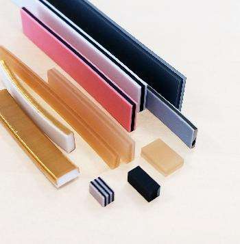
An elastomeric connector is a connector made with a silicone base, with an alternance of conductive and electric isolating layers. Elastomeric connectors are assembled mechanically without soldering.
Those elastomeric connectors are also named ZEBRA connectors, because of the alternating black and white strip (remembering the animal).
Elastomeric connector’s none-conductive zone are made of neutral silicone (not charged). Silicone is the base material due to its excellent properties of aging, chemical stability, electric reliability, and mechanic behavior regarding shocks and vibrations.
Conductive zones can be made up of :
Charged silicone : Carbon/Graphite or Silver (much rarer)
Representation of a carbon-filled elastomer connector (Type ZEBRA)

Standard dimensions of elastomer connectors (Ni/C or Silver filled silicone)

Copper-beryllium wires, which can be gold-plated on the surface (electrical conductivity is better with these elastomeric connectors).
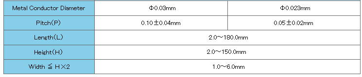
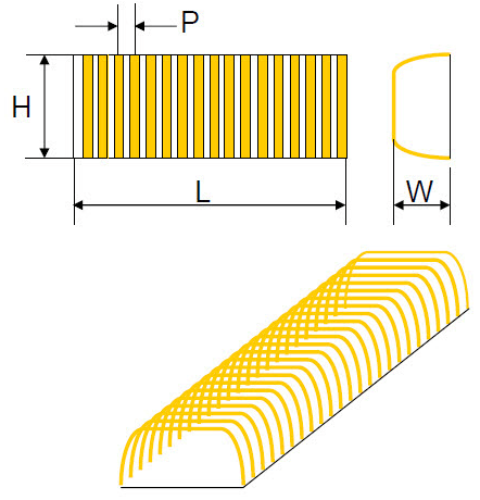
Plan of an elastomeric connector with copper beryllium (CuBe) wires

Standard dimensions of elastomer connectors (Copper Beryllium)
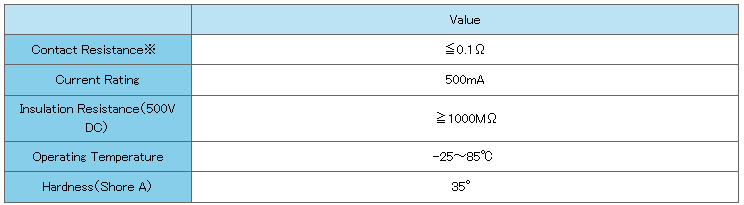
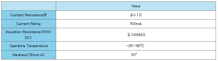
Standard technical specifications for elastomeric connectors (Copper Beryllium)
There is also a version with a side connection, particularly suitable for connections from LCD screens to PCBs or from PCB to PCB for higher currents.
Drawing of an elastomer connector with lateral Copper Beryllium (CuBe) wires
Standard dimensions of elastomer connectors (copper-beryllium) on the sides

Standard specifications for elastomeric (copper-beryllium) side connectors
This alternation of charged silicone and neutral silicone is done on Z axis, for elastomeric connectors in line. It is possible to add isolating silicone layers on both sides of the connector to increase its rigidity and/or isolate it from components and surrounding electric tracks. This isolating silicone thickness on the side of the elastomeric connector is from 0.05 mm minimum to 1.5 mm. The hardness of this silicone can be adjusted as needed.
For this type of elastomeric connector in Z axis, the ratio between the height and the width must be at least 1.5 mm to guarantee the mechanical resistance of the connector.

Alternating conductive/non-conductive strips can also be used in the XY plane, in the case of matrix connectors. These are equidistant contact points with the same metrics (0.05mm pitch and minimum 0.03mm diameter) as an elastomeric connector in the Z axis.


In both configurations, the materials used are the same (neutral silicone, and filled silicone and/or beryllium copper wires).
How does elastomeric connectors work?
The density of the alternating contact areas is elevated on this type of connector (0.1 mm pitch or 0.05 mm in standard). This density is much higher than the connection tracks on a PCB or on an LCD connection for example. Therefore, each track on the PCB will be in contact with at least one conductive area of the elastomeric connector, and there will be at least one isolating layer between two tracks of the PCB. Hence, the risk of short circuit is null.
The assembly of an elastomeric connector is done by mechanic compression.
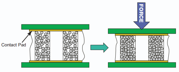
The metal particles mixed with the silicone make it conductive, creating thousands of passages that conduct electricity. This phenomenon is reinforced by the connector’s slight compression. The insulating zones of non-conductive silicone isolate the various contact points to prevent short circuits on the PCB.
How do you integrate an elastomer connector into your electronic assembly?
Elastomeric connectors must be assembled using a mechanical holster to ensure that the conductive zones are positioned with the PCB or sensor tracks.
Without this type of positioning structure, there is a risk that the connector will not be in contact with the electrical tracks due to buckling of the connector or displacement on the PCB.
In both configurations, the materials used are the same (neutral silicone, and filled silicone and/or beryllium copper wires).
How do you use elastomeric connectors?
The density of the alternating contact zones on this type of connector is very high (steps of 0.1 or 0.05mm as standard). This density is much higher than that of the connection tracks on PCBs or LCD connections, for example.
As a result, each track on the PCB will be in contact with at least one conductive area of the elastomeric connector, and there will be at least one insulating layer between two tracks on the PCB. This eliminates the risk of short circuits.
An elastomeric connector is assembled by mechanical compression.
The metal particles mixed with the silicone make it conductive, creating thousands of passages that conduct electricity. This phenomenon is reinforced by the connector’s slight compression. The insulating zones of non-conductive silicone isolate the various contact points to prevent short circuits on the PCB.
How do you integrate an elastomer connector into your electronic assembly?
Elastomeric connectors must be assembled using a mechanical holster to ensure that the conductive zones are positioned with the PCB or sensor tracks.
Without this type of positioning structure, there is a risk that the connector will not be in contact with the electrical tracks due to buckling of the connector or displacement on the PCB.
In both configurations, the materials used are the same (neutral silicone and filled silicone and/or beryllium copper wire).
How do you use elastomeric connectors?
The density of the alternating contact zones on this type of connector is very high (0.1 or 0.05mm steps as standard). This density is much higher than that of the connection tracks on PCBs or LCD connections, for example.
As a result, each track on the PCB will be in contact with at least one conductive area of the elastomeric connector, and there will be at least one insulating layer between two tracks on the PCB. This eliminates the risk of short circuits.
An elastomeric connector is assembled by mechanical compression.
The metal particles mixed with the silicone make it conductive, creating thousands of passages that conduct electricity. This phenomenon is reinforced by the connector’s slight compression. The insulating zones of non-conductive silicone isolate the various contact points to prevent short circuits on the PCB.
How do you integrate an elastomer connector into your electronic assembly?
Elastomeric connectors must be assembled using a mechanical holster to ensure that the conductive zones are positioned with the PCB or sensor tracks.
Without this type of positioning structure, there is a risk that the connector will not be in contact with the electrical tracks due to buckling of the connector or displacement on the PCB.


Why are elastomeric connectors used?
Elastomeric connectors are made from non-abrasive materials (neutral and conductive silicones). These materials do not damage the contact areas on PCBs or LCD screens, for example.
The natural resilience of silicone ensures that numerous compression (assembly) and decompression (disassembly) cycles can be carried out without any risk of altering the mechanics of the elastomer connector.

These elastomer connectors are widely used for high-density connections between two parallel PCBs, or to connect sensors or interfaces (microphone, loudspeaker, LCD screen).
One of the advantages of the high density of contact points on elastomer connectors is the possibility of passing mixed signals with the same elastomer connector.

The reliability and manufacturing process of these elastomer connectors mean that they are widely used in many fields. These connectors are widely used for both low-cost consumer applications and high-value-added on-board flight computers.
A few examples of elastomer connector applications

Elastomer connectors in payment terminals
Our main customers use these elastomer connectors to make electrical connections in payment terminals. In these assemblies, the elastomer connectors are integrated into the equipment’s plastic chassis. They thus guarantee electrical contact in an environment subject to shocks and vibrations (e.g. a bank card payment terminal).

Elastomer connectors on test supports
The high density of connection of elastomeric connectors make them a good technical solution for PCB’s test devices. Notably, matrix elastomeric connectors.Pitches of 0.1 or 0.05 mm on the plane offer plenty of permanently and simultaneously accessible contact points without risk of short circuit. Unlike mechanical touch tips which have to be adjusted,targeted and are very localized.
The composition of elastomeric connectors, mostly made from silicone, allow it to withstand several thousand of cycles of compression and decompression without deteriorating and without imposing strong mechanical stress on PCB’s contact points.

Elastomeric connector in a customised, watertight flexible connector
Elastomeric connectors offer ample possibilities of customization on connectors. They can be integrated into a frame to make a plug with high density of contact points.Their silicone base also ensures a water tightness level IP (to fluids and particles) that isn’t found with mechanical connectors. This functionality makes it a strategic choice, especially for connectors with medical application.
Why use an elastomer connector rather than a mechanical connector?
In increasingly denser electronic assembly, electronic mechanical connectors and other mechanical contact points quickly reach their limits. Given that those mechanical connectors (often pin or tip systems) cannot reach densities and a precision of connection as high as elastomeric connectors.
Elastomeric connectors also simplify electronic assemblies (with lower tolerance limits),while reducing costs (no tooling cost) and lead time (not tips conception or custom pins).
Elastomeric connectors, made from silicone, also have much higher mechanical resistance to vibrations and shocks compared to pure metal connectors.
In terms of cost, unlike mechanical connectors, no tools are necessary to produce elastomeric connectors. As pitch and space requirements, the more elastomeric connectors will be a pertinent technical and economical solution compared to mechanical connectors.
How do you size and choose the right elastomeric connector?
Elastomeric connectors are made on request according to the application’s specified requirements and configuration. This process leaves more wiggle room to integrate those electronic assembly’s components.
However, maximal dimensions are limited. Around 120-150 mm long, 5 mm wide and 10-20 mm high. Those limits are rarely reached on electronic assembly.
Length of the elastomer connector
The elastomeric connector must be sightly larger than the space between the first contact track and the furthest one.
We recommend making it go over by 0.5 or even 1 mm on each side to ensure the electric contact.
Width of the elastomer connector
The width of the elastomer connector must be determined by 3 parameters:
- Reliability : The contact range must be sufficient
- Force : The wider the elastomer connector, the greater the compression force required. Be careful not to oversize the connector.
- Stability : You need to find the right compromise to prevent the connector buckling (flexing) during compression assembly and to avoid excessive compression forces and bulk.
The recommended formula for calculating width is as follows:
Width = Height / 2.5 (recommended between 1 and 5mm).

Calculating the resistance of an elastomeric connector
The width of the tracks and therefore the overall length of the elastomeric connector can also be determined by the resistance of the connector (dependent on the size of the contact area).
For a carbon-filled silicone elastomer connector, the resistance is calculated as follows:
R = ( 60 x H ) x (Ew x W)
Where :
W = Width of elastomeric connector
Ew = Width of conductive contact area (conductive silicone only)
H = Height of elastomer connector
Height of elastomer connector :
Elastomer connectors must be slightly compressed to ensure electrical contact, limit play in assemblies and withstand vibration.
For elastomer connectors made exclusively of silicone, the recommended compression ranges from 5% to 25% (the overall height of the connector also affects the compression ratio). The height therefore indirectly depends on the compression force required to compress the elastomeric connector.
To calculate the compression force required for filled silicone elastomer connectors, you can use the following formula :
F = 9 x D x W x L x 9.8×10⁻³
Where
F = Force (N)
D = H – H1
With
H1 = Height of compressed elastomeric connector (mm)
H = Height of uncompressed elastomeric connector (mm)
W = Width of elastomeric connector (mm)
L = Length of elastomer connector (mm)
Do you have a question about using elastomeric connectors for your application?
Thank you for reading this article to the end!
If you have any questions, need samples or any other technical information:
You can get in touch with us using the chat or by sending us a message using the contact form just below.


